

How To Draw Planes In Cubic Unit Cell
Lattice Planes and Miller Indices (all content)
Note: DoITPoMS Teaching and Learning Packages are intended to be used interactively at a figurer! This impress-friendly version of the TLP is provided for convenience, only does not brandish all the content of the TLP. For case, any video clips and answers to questions are missing. The formatting (page breaks, etc) of the printed version is unpredictable and highly dependent on your browser.
Contents
Chief pages
Additional pages
Aims
On completion of this TLP you should:
- Understand the concept of a lattice plane;
- Be able to determine the Miller indices of a plane from its intercepts with the edges of the unit of measurement cell;
- Be able to visualise and depict a plane when given its Miller indices;
- Exist aware of how knowledge of lattice planes and their Miller indices can help to understand other concepts in materials science.
Earlier yous start
You should sympathize the concepts of a lattice, unit cell, crystal axes, vrystal system and the variations, primitive, FCC, BCC which brand upwards the Bravais lattice.
Yous might besides like to wait at the TLP on Atomic Scale Structure of Materials.
Yous should empathize the concepts of vectors and planes in mathematics.
Introduction
Miller Indices are a method of describing the orientation of a aeroplane or set of planes within a lattice in relation to the unit prison cell. They were developed by William Hallowes Miller.
These indices are useful in agreement many phenomena in materials science, such every bit explaining the shapes of single crystals, the form of some materials' microstructure, the estimation of X-ray diffraction patterns, and the movement of a dislocation, which may determine the mechanical properties of the material.
How to alphabetize a lattice plane
The next three animations take y'all through the nuts of how to index a plane. Click "Commencement" to begin each animation, then navigate through the pages using the buttons at the bottom right.
Parallel lattice planes
This animation explains the relationships between parallel planes and their indices. Click "Start" to begin and utilize the buttons at the bottom right to navigate through the pages.
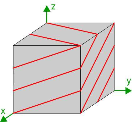
Lattice planes can be represented past showing the trace of the planes on the faces of i or more unit cells. The diagram shows the trace of the (23) planes on a cubic unit cell.
How to describe a lattice plane
Bracket Conventions
In crystallography there are conventions as to how the indices of planes and directions are written. When referring to a specific plane, "circular" brackets are used:
(hkl)
When referring to a prepare of planes related past symmetry, then "curly" brackets are used:
{hkl}
These might be the (100) type planes in a cubic arrangement, which are (100), (010), (001), (00),(00) and (00) . These planes all "look" the same and are related to each other by the symmetry elements present in a cube, hence their different indices depend only on the way the unit jail cell axes are defined. That is why information technology useful to consider the equivalent (010) set of planes.
Directions in the crystal can be labelled in a similar way. These are effectively vectors written in terms of multiples of the lattice vectors a, b, and c. They are written with "foursquare" brackets:
[UVW]
A number of crystallographic directions can also be symmetrically equivalent, in which example a set of directions are written with "triangular" brackets:
<UVW>
Vectors and Planes
Information technology may seem, after considering cubic systems, that whatever lattice airplane (hkl) has a normal direction [hkl]. This is not always the case, as directions in a crystal are written in terms of the lattice vectors, which are not necessarily orthogonal, or of the same magnitude. A elementary example is the case of in the (100) plane of a hexagonal arrangement, where the direction [100] is actually at 120° (or 60° ) to the plane. The normal to the (100) plane in this instance is [210]
VR rotating image
Weiss Zone Law
The Weiss zone law states that:
If the management [UVW] lies in the aeroplane (hkl), and so:
hU +kV +lW = 0
In a cubic organization this is exactly analogous to taking the scalar product of the management and the plane normal, so that if they are perpendicular, the angle betwixt them, θ, is ninety° , so cosθ = 0, and the direction lies in the plane. Indeed, in a cubic system, the scalar product can exist used to determine the bending between a management and a plane.
Nevertheless, the Weiss zone police is more full general, and can be shown to work for all crystal systems, to decide if a direction lies in a plane.
From the Weiss zone police the following rule tin can be derived:
The direction, [UVW], of the intersection of (h 1 chiliad 1 l 1) and (h two m 2 l two) is given by:
U =k 1 l 2 −k 2 l ane
5 =l i h 2 −l two h 1
Westward =h 1 k 2 −h 2 k one
As it is derived from the Weiss zone constabulary, this relation applies to all crystal systems, including those that are not orthogonal.
Examples of lattice planes
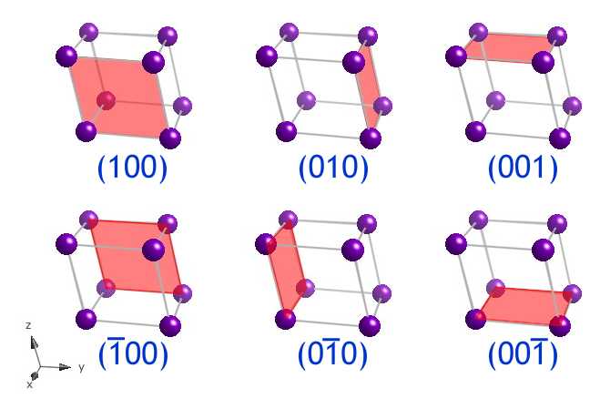
The (100), (010), (001), (00), (00) and (00) planes form the faces of the unit cell. Here, they are shown as the faces of a triclinic (a ≠ b ≠ c, α ≠β ≠γ) unit prison cell . Although in this prototype, the (100) and (00) planes are shown as the forepart and back of the unit prison cell, both indices refer to the aforementioned family of planes, every bit explained in the animation Parallel lattice planes. It should exist noted that these six planes are not all symmetrically related, as they are in the cubic organization.
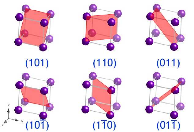
The (101), (110), (011), (ten), (10) and (01) planes course the sections through the diagonals of the unit jail cell, along with those planes whose indices are the negative of these. In the prototype the planes are shown in a different triclinic unit cell.
The (111) blazon planes in a face centred cubic lattice are the close packed planes.
Click and drag on the image below to come across how a close packed (111) plane intersects the fcc unit of measurement cell.
VR rotating image
Draw your own lattice planes
This simulation generates images of lattice planes. To run into a airplane, enter a set of Miller indices (each index between 6 and −6), the numbers separated by a semi-colon, so click "view" or press enter.
Applied Uses
An agreement of lattice planes is required to explain the grade of many microstructural features of many materials. The faces of single crystals form on certain lattice planes, typically those with low indices.
In a similar way, the form of the microstructure in a polycrystalline fabric is strongly dependent on lattice planes. When a new phase of material forms, the surfaces tend to be aligned on low index planes, every bit with single crystals. When a new solid phase is formed in some other solid, the interfaces occur on along the most energetically favourable planes, where the two lattices are most coherent. This leads to plate-similar precipitates forming, at specific angles to each other.
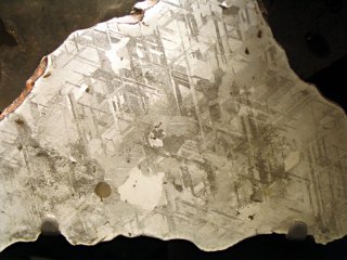
Department through an Atomic number 26-Ni meteorite showing plates at 60° to each other
![]() DoITPoMS standard terms of employ
DoITPoMS standard terms of employ
Ane method of plastic deformation is past dislocation slip. Understanding lattice planes, and directions is essential to explicate why dislocations move, combine and tangle in the observed manner. More data can be obtained in the TLP - 'Skid in Single Crystals'
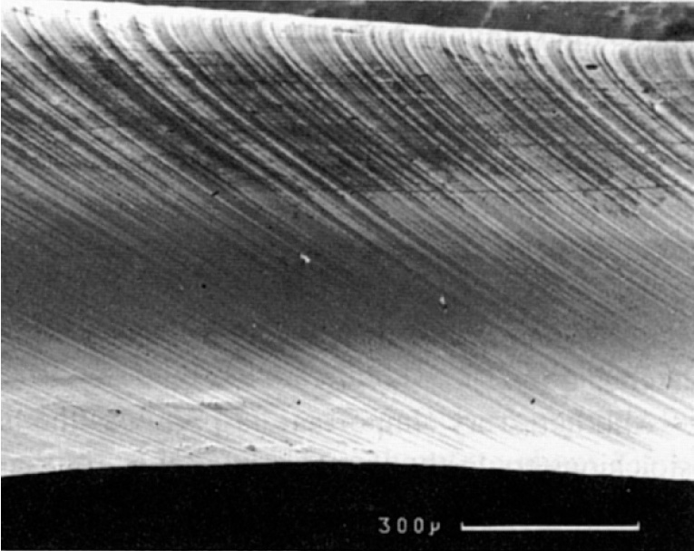
A scanning electron micrograph of a single crystal of cadmium
deforming past dislocation slip on 100 planes, forming steps
on the surface
![]() DoITPoMS standard terms of use
DoITPoMS standard terms of use
Twinning is where a part of the crystal is "flipped" to form a mirror image of the rest of the crystal, reflected in a detail lattice airplane. This can either occur in annealing, or as a mechanism of plastic deformation.
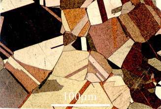
Annealing twins in contumely (DoITPoMS micrograph library)
Ten-ray diffraction is a method of determining the crystal construction of a textile. By interpreting the diffraction patterns as reflections from lattice planes in the cloth, the structure can be determined. More than information tin be obtained in the TLP - '10-ray diffraction '
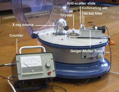
Apparatus for carrying out unmarried crystal X-ray diffraction.
Worked examples
Example A
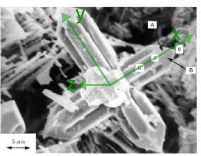
The figure beneath is a scanning electron micrograph of a niobium carbide dendrite in a Iron-34wt%Cr-5wt%Nb-iv.5wt%C alloy. Niobium carbide has a confront centred cubic lattice. The specimen has been deep-etched to remove the surrounding matrix chemically and reveal the dendrite. The dendrite has 3 sets of "arms" which are orthogonal to one another (i fix pointing out of the plane of the image, the other ii sets, to a good approximation, lying in the plane of the image), and each arm has a pyramidal shape at its cease. It is known that the crystallographic directions along the dendrite arms represent to the < 100 > lattice directions, and that the management ab labelled on the micrograph is [ten] .
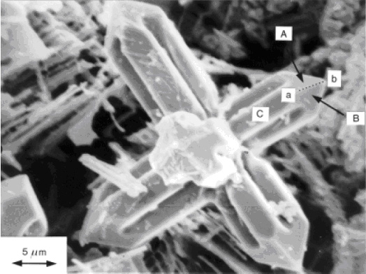
sourced from Dendritic Solidification
1) If signal c (not shown) lies on the axis of this dendrite arm, what is the direction cb ? Index face C , marked on the micrograph.
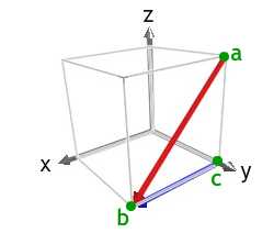
The diagram shows the [10] direction in carmine. The [100] direction is a < 100 > type management that forms the observed acute angle with ab, and can exist used every bit cb. Of the < 100 > type directions, we could too have used [00] .
Using a correct handed set of axes, we then have z-centrality pointing out of the plane of the image, the x-axis pointing along the direction cb, and the y-axis pointing towards the top left of the image.
Face up C must comprise the direction cb, and its normal must point out of the plane of the epitome. Therefore face up C is a (001) plane.
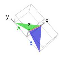
2) The four faces which lie at the terminate of each dendrite arm have normals which all brand the same bending with the direction of the arm. Observing that faces A and B marked on the micrograph both contain the management ab , and noting the full general directions along which the normals to these faces point, index faces A and B .
Both faces A and B have normals pointing in the positive 10 and z directions, i.e. positive h and l indices. Face A has a positive one thousand alphabetize, and face B has a negative one thousand index.
The morphology of the ends of the arms is that of one-half an octahedron, suggesting that the faces are (111) blazon planes. This would make face A, in green, a (111) airplane, and face up B, in blue, a (ione) plane. As required, they both contain the [x] management, in cerise.
Case B
1) Work out the common direction between the (111) and (001) in a triclinic unit prison cell.
The relation derived from the Weiss zone law in the section Vectors and planes states that:
The direction, [UVW], of the intersection of (h 1 yard i l 1) and (h 2 k 2 l 2) is given by:
U =thousand one l 2 −one thousand ii l one
V =l 1 h 2 −l 2 h one
W =h 1 one thousand two −h 2 k 1
We tin can use this relation as it applies to all crystal systems, including the triclinic organization that we are considering.
We take h 1 = 1, 1000 1 = i, l ane = 1
and h 2 = 0, k 2 = 0, l 2 = 1
Therefore
U = (1 × 1) - (0 × i) = one
V = (1 × 0) - (i × one) = −1
W = (one × 0) - (0 × 1) = 0.
So the common direction is:
[ane0] .
This is shown in the prototype below:
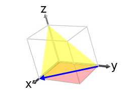
If nosotros had defined the (001) plane as (h 1 k 1 fifty 1) and the (110) plane as (h 2 k 2 l 2) then the resulting direction would have been, [10] i.e. anti-parallel to [one0] .
2) Employ the Weiss zone law to evidence that the direction [one0] lies in the (111) plane.
We have U =i, 5 =−ane, W =0,
and h = 1, thou = i, l = i.
hU +kV +lW = (1 × 1) + (1 × −1) + (1 × 0) = 0
Therefore the direction [ane0] lies in the plane (111).
Summary
Miller Indices are the convention used to label lattice planes. This mathematical clarification allows us to define accurately, planes inside a crystal, and quantitatively analyse many problems in materials science.
Questions
Game: Identify the planes
Quick questions
You should be able to answer these questions without too much difficulty afterward studying this TLP. If not, then yous should go through it again!
-
Which one of the following statements about the (iv) and (2one) planes is fake?
-
Does the [anetwo] direction lie in the (30) airplane?
-
When writing the index for a set of symmetrically related planes, which type of brackets should be used?
-
Which of the <110> blazon directions prevarication in the (112) plane?
-
What is the common direction between the (1 ) and (33) planes?
-
Which set of planes in a cubic-close-packed structure (such as copper) is close packed?
Open up-ended questions
The post-obit questions are not provided with answers, simply intended to provide food for thought and points for further discussion with other students and teachers.
-
Do sketching some lattice planes. Make sure y'all can describe the {100}, {110} and {111} blazon planes in a cubic system.
-
Draw the trace of all the (21) planes intersecting a cake 2 × ii × 2 cake of orthorhombic (a ≠ b ≠ c, α = β = γ = 90°) unit cells.
-
Sketch the arrangement of the lattice points on a {111} blazon aeroplane in a face centred cubic lattice. Do the aforementioned for a {110} blazon plane in a body centred cubic lattice. Compare your drawings. Why do y'all think the {110} blazon planes are oft described as the "most shut packed" planes in bcc?
Going further
Books
[1] D. McKie and C. McKie, Crystalline Solids , Thomas Nelson and Sons, 1974.
A very comprehensive crystallography text.
[2] C. Hammond, The Basics of Crystallography and Diffraction , Oxford, 2001.
Chapter v covers lattice planes and directions. The residue of the book gives an introduction to crystallography and diffraction in general.
[three] B.D. Cullity, Elements of Ten-Ray Diffraction , Prentice Hall, 2003.
Covers X-Ray diffraction in particular. Affiliate ii covers the crystallography required for this.
[4] C. Kittel, Introduction to Solid State Physics, John Wiley and Sons, 2004.
Affiliate 1 covers crystallography. The volume then goes on to cover a wide range of more advanced solid state science.
Cómo indexar united nations plano de una carmine
Las siguientes tres animaciones muestran los fundamentos básicos para calcular los parámetros del cherry-red. Haz click en "Inicio" para que comience cada animación, y luego navega a través de las páginas usando los botones situados en la parte inferior derecha.
如何标注一个晶格面
以下的三个动画 课程将让你了解关于标注晶格面的基本知识。点击'开始'来开始每个动画课程,然后用右下角的按钮来进入下一页。
Как обозначать плоскость кристаллической решётки
Следующие три анимации покажут основы того, как обозначать плоскость. Нажмите кнопку "Пуск", чтобы запустить каждую из анимаций, а затем управляйте анимацией с помощью кнопок, расположенных в правом нижнем углу.
Academic consultant: Noel Rutter (Academy of Cambridge)
Content development: Peter Marchment
Photography and video: Brian Hairdresser and Carol Best
Web development: David Brook and Lianne Sallows
Translation: Jing Qiu, Kansong Chen, Ana Tabalan-Bailey, Marta Sanchez, Juan Vilatela
DoITPoMS is funded by the United kingdom Center for Materials Instruction and the Section of Materials Scientific discipline and Metallurgy, University of Cambridge
Additional support for the evolution of this TLP came from the Worshipful Company of Armourers and Brasiers'

How To Draw Planes In Cubic Unit Cell,
Source: https://www.doitpoms.ac.uk/tlplib/miller_indices/printall.php
Posted by: hubbardwhationam.blogspot.com
0 Response to "How To Draw Planes In Cubic Unit Cell"
Post a Comment